This post is very old and full information that is all over the place. Please go here for a summary of the progress.
PROOF OF CONCEPT PROTOTYPE
I have been researching 3d scanners forever now. Amount of data I collected, the number designs I have trashed, the time I spent looking for compatible parts, the time I spent choosing the programming language responsive, reliable, and flexible enough to control the hardware are way too many to count.
I finally decided on a design and started working on a prototype of a small part of the system a couple months ago. It is a very cheap proof of concept rather than a prototype, but it still is good enough for me to help predict the problems that I may face later in the building and programming phase. In fact, I ran into my first problem after I finished building the hardware and while writing the code for the point coordinate streaming into Houdini.
I need to discover the algorithms required to recreate a point cloud from distance information and stream their coordinates to Houdini. Resulting point cloud will be blurry and smudgy due to the parts used in the hardware. Infrared beam of the distance sensor is quite wide according to its specifications, and outdated controller chips that are not responsive enough. Everything aside, this will give me a starting point. In short, my goal for this project is to figure out a way to convert the distance information into 3d cartesian information and plot it in Houdini.
UPDATE
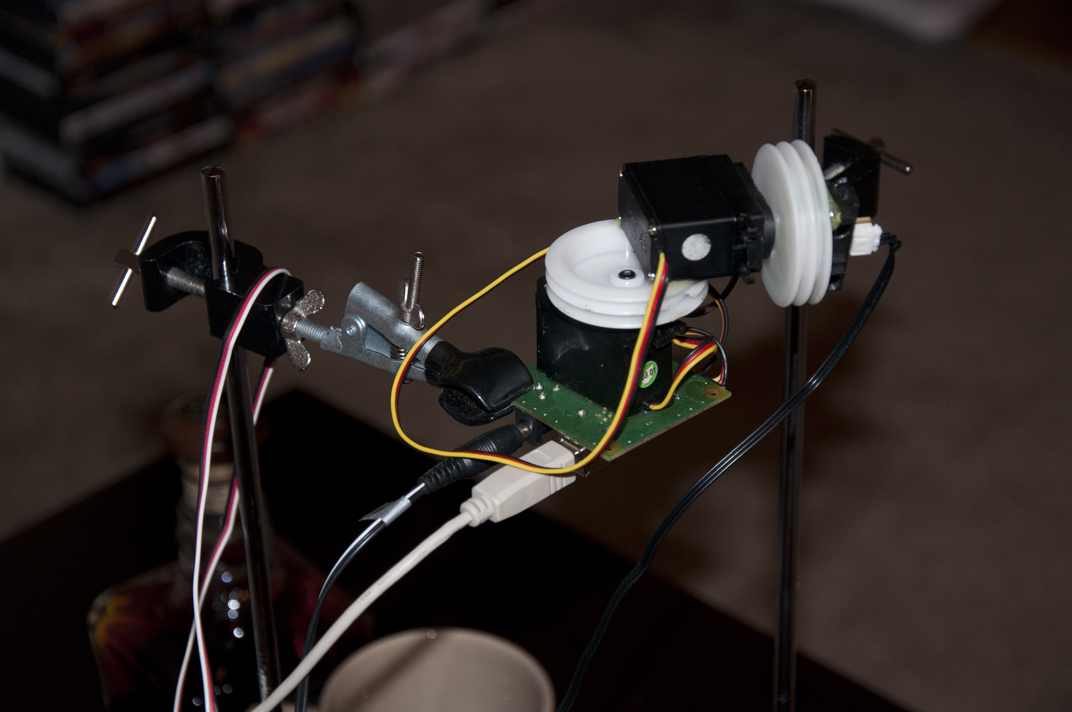
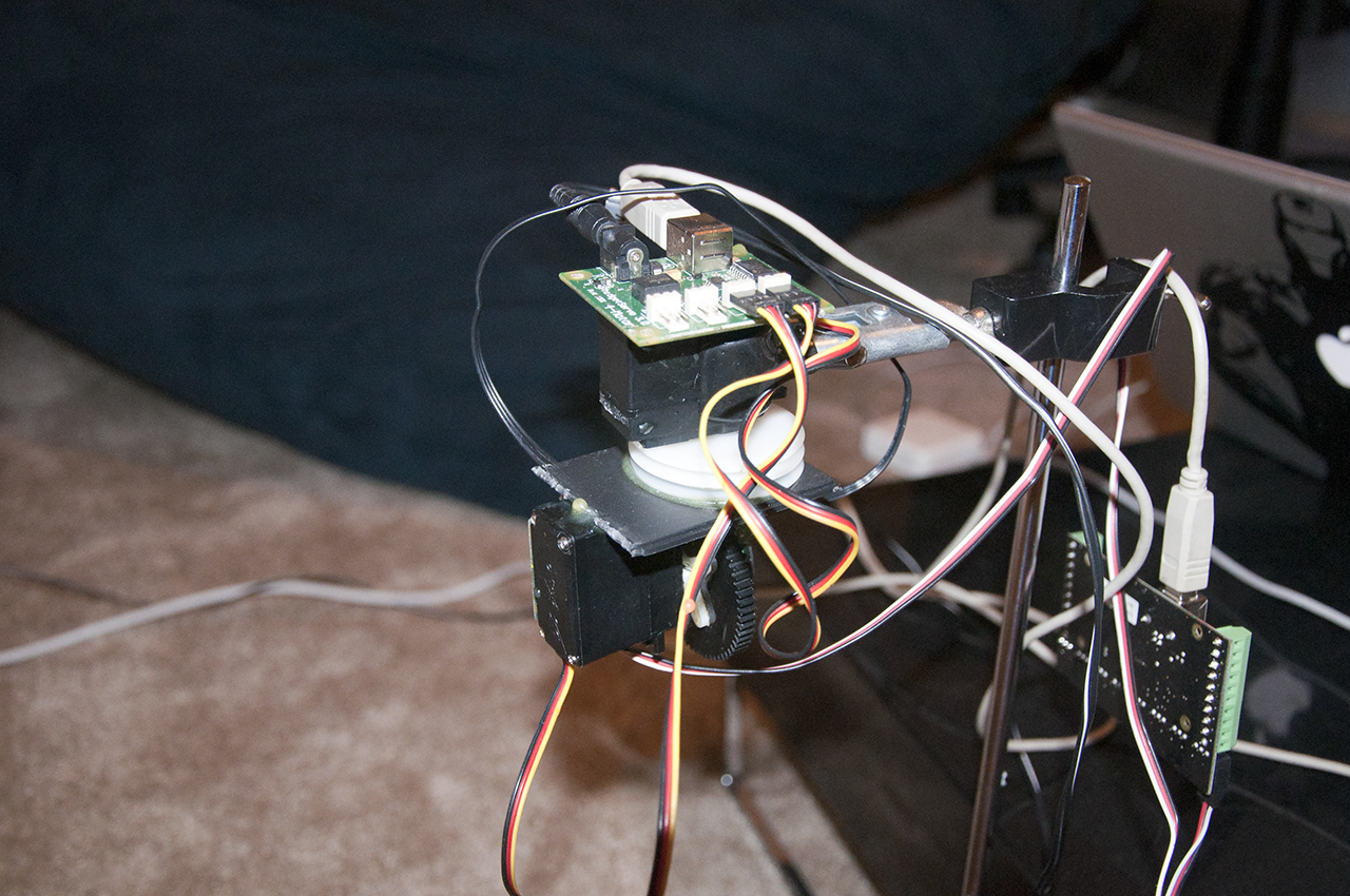
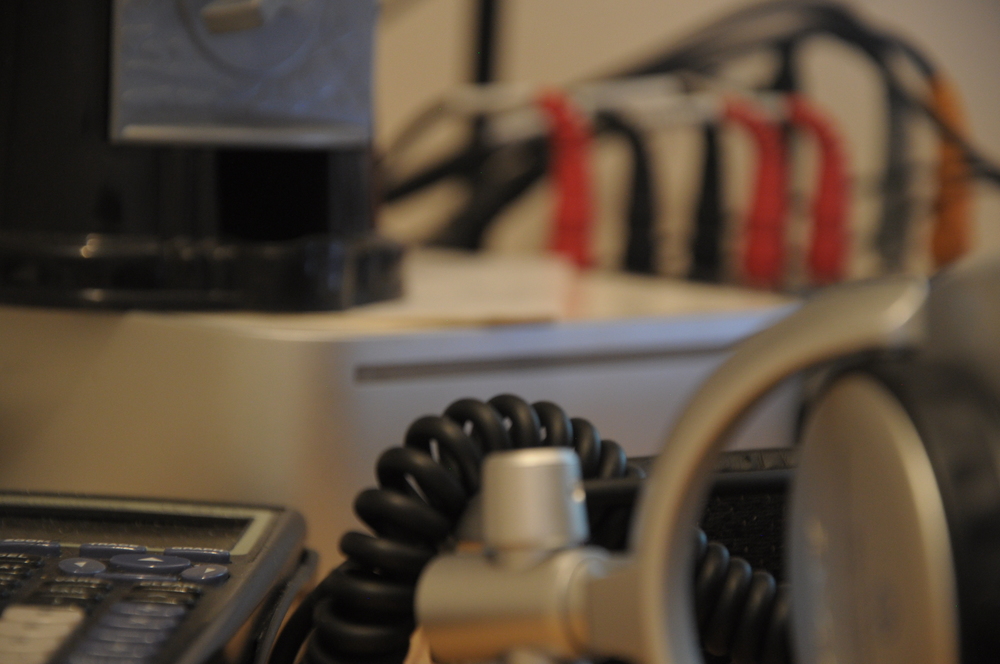
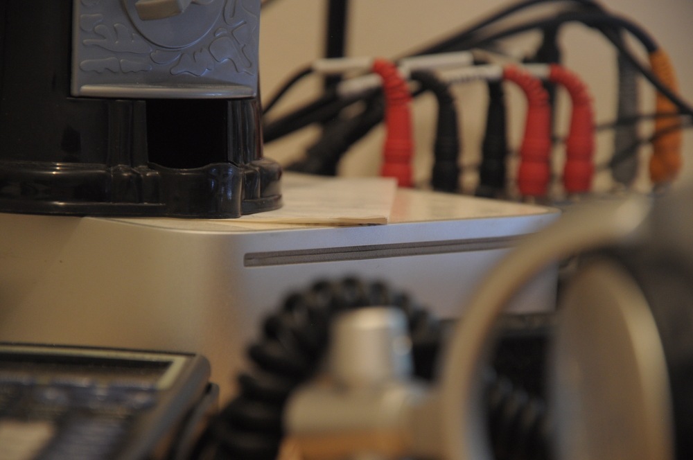
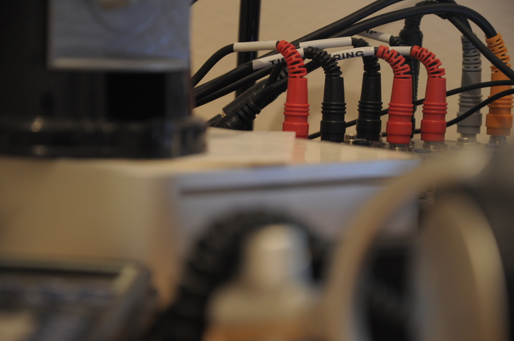
Here is a picture of the hardware I put together in an hour with epoxy, hot glue, and very cheap and inaccurate hardware. Just barely enough for a proof of concept.
Two servo motors are put together in a pan and tilt setup. At the end of the upper servo there is a IR distance sensor that can measures distances between 10-80cm. The servos are connected to a usb servo controller, and the IR distance sensor is connected to a USB interface board.
Servos are Hitec, usb interface and servo control boards are Phidgets, and the distance sensor controller is also Phidgets but the sensor itself is Sharp.
UPDATE
Random test data generation with Python was easier than I expected. So instead of trying to pipe random data into Houdini, I decided to go ahead and triangulate an actual scan. I realized that the simple trigonometry I expected to work had a fatal flaw. That is after I put hours of work into solving my problem with simple triangles.
Solution was using sphere and arc calculations instead of just triangles. The formula to recreate a point cloud of the scan is not complete yet, but it is nearly there. Once the formula is complete, I will work on piping the point cloud from the telnet port directly into Houdini instead of saving *.geo files and loading them into Houdini later. This piece of code may also be used in a later iteration of the scanner algorithm for developing a "real-time" scanning mode where the point cloud is generated on the fly while the object is still being scanned.
Since I have been working on the IR sensor since the start, all of the code is already optimized for the IR version. So I will have more time to prepare a demo.
UPDATE
I have tinkered around with the hardware design a bit to make the rotations from the nodal point. Parallax, and warping are still there but the results are much better.
Due to the IR noise in the environment I had to change the algorithm to take more measurements per angle and average them. (Reading thru this post much later, I realize that using a Gaussian least squares method of all the measurements per point might have been much better) As a result, performance took a huge hit, but the results are looking much better. I am looking at roughly 30 minutes per scan now.
As I stated before on an update, simple triangulation, trigonometry, and arc calculations are not working in this case. Arc calculations got close but the elegant solution is to coordinate space conversion.
I am scraping the telnet plans for now since I found a way to run the script in Houdini. To iterate, I already could run the script in houdini but it could only rotate the servos and take measurements. Now I found a way to actually use that info to create the point cloud in real-time.
Houdini Python is becoming clearer to me now. The alienating Houdini object model, and hou module are easier to control. I will make the code add an "add" node, and add points to it as they are scanned for real time Houdini scanning.
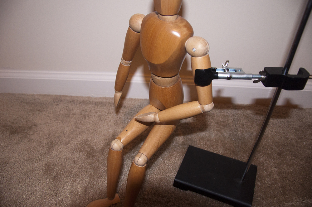
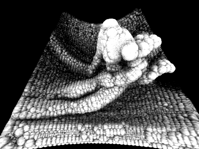
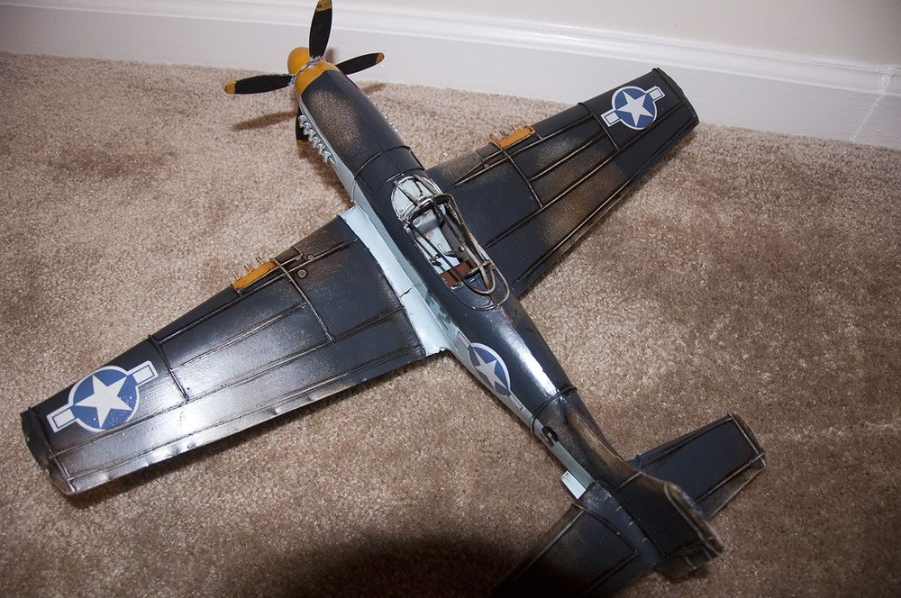
Below is the mannequin I tried scanning first. And next to iy is the resulting point cloud that i used to instance spheres on. Following is the same with a metal P-51 Mustang model.
 |
 |
 |
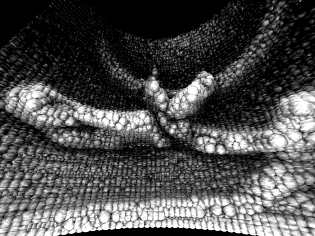 |
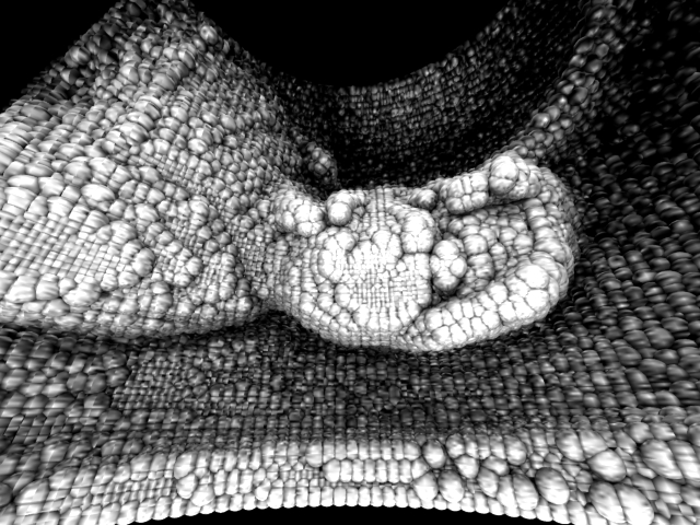
And finally I decided to scan my own head and torse... horrible stuff on below left.
Notice how the IR beam gets diffused in hair, and how the body temperature is blurring the sensor's vision. My left eyeball is clearly visible in the image since it reflected the IR beam back, but the rest is just diffused and blurred except for the shirt.
The IR system is cheap but has some fundemental flaws such as
- Wide beam diameter causes blurred results,
- IR filter on the CCD doesn't like warm/hot surfaces,
- IR beams are easily reflected from metals and other semi reflective surfaces to a completely different direction resulting in empty spots in the point cloud.
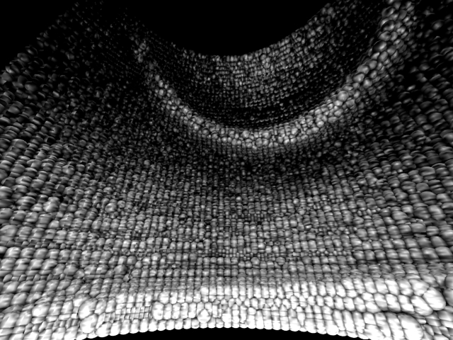
Below right is an empty scan point cloud to compare the background from all these renders.
 |
 |
UPDATE
I have spent summer experimenting with different techniques, and decided that I would use a technique called structured light scanning. Its price, ease of setup, and most importantly its performance were key factors in my decision.
My infrared scanner was limited to the refresh rate of the controller board and distance sensor I was using, and an ideal upgrade would be designing a brand new circuit using a IC called TDC-GPX, and involve a lot of low level programming. Result would be a LIDAR which would be very hard to sync with other scanner rigs in the same room due to its insane refresh rates.
One of the other techniques I experimented with was building my own distance sensor using a 1080p camera and a laser pointer. It was limited to 24 frames per second, was prone very much to image noise, and had to be calibrated very precisely due to the 1080p resolution.
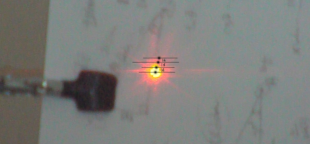
The idea was that if you mount a laser pointer on a camera, parallel with camera lens, the farther laser dot gets away from the center of the recorded image, the closer the object was. Needless to say, this idea was scrapped due to the high cost of building each sensor, and sensor performance. To the left is a layered image from the results of my experiment.
This works essentially the same way the IR distance sensor worked. This works in 2 dimensions and has much higher resolution.
 |
 |
 |
 |
 |
 |
 |
 |
 |
Other experiments I did were all with using off the shelf software. One of them that I will share some info about is called focus stacking, and the reason I want to share it is because it is an ingenious way of generating a 3D mesh. Something so simple yet I personally wouldn't think of it at all.
Documentation on the software developers web site does not specify how it works, but from my understanding it relies on edge detection. Here is a pipeline that I believe should describe the process more or less
- Take focus stack photos from a locked camera. Only difference between the photos should be tiny increments of focus. Camera stores focus distance along with other parameters to the EXIF portion of the image.
- Software analyzes the stacked images for sharpness by edge detection and assignes sharp pixels a distance value based on the EXIF focus distance. Blurry pixels are skipped.
- Result is essentially a z-depth map without a projection matrix.
Easy, yes. Simple, yes. Cool, incredibly. Accurate, not the slightest bit... This will not pick up anything smooth even if it is in focus, like walls, table tops, lcd displays, and etc. Also it depends directly on the resolution of the camera for its precision. For further info google helicon, or focus stacking.
I decided on structured light after I saw a demo video by Kyle Mcdonald.
Hardware required would be relatively cheap, and the code didn't seem to be too complicated either. OpenCV library initially released by Intel that is compatible with practically any imaging hardware isn't too hard to code for either. Everything seemed so simple at the beginning yet setting up the environment proved not to be.
I have been away from proper programming for far too long. Python and MEL and similar stuff does not count. Matching a proper OS with a decent IDE with access to OpenCV and its C++ bindings was not an easy decision. I jumped back and forth between Ubuntu and OSX for quite a long time. Xcode is pretty and integrated, but getting 3rd party frameworks and libraries to compile took a while to figure out. Needless to say, I decided to stay in Ubuntu for the time being, but the environment in OSX is ready and waiting. The current environment I am using is ubuntu, NetBeans, C++ and its OpenCV API.
Next thing on the list was matching hardware with the computing environment. I purchased two PS3 Eye cameras online. This is an awesome camera, it does 120fps at 320x240, and 60fps at 640x480 among other modes. It costs about ~35 usd. It is easy to modify the m12 lens mount and attach other lenses too. You can even replace the m12 mount with a CS mount. Sony does not include USB drivers for the PS3 camera, which means its drivers are supported by the open source/hacker/diy community. There is a very good document on how to set it up [ here ].
UPDATE
I have been sharpening my C++, trying to get used to namespaces and the syntax. I am only using includes that behave the same in all operating systems, as always, trying to keep the code platform independent.
I have the part of the code that projects the patterns and records them. 60 times every second, giving me a practical frame rate of 15 frames per second with 3 patterns and 1 white frame. Of course this can be easily increased to 120 times a second, but it would require a projector with 120Hz refresh rating as well as lower resolution of the captured images.
There is a sync issue between the camera and the projector as top half of the previous pattern can be seen in the captured images, I believe that the issue is caused by the refresh type of the dlp chip in the projector since the camera uses a global shutter CCD system. I may loose even more frames per second to compensate for it.
I am ignoring this sync issue for the time being and focusing more on the actual pattern comparison algorithm that will create the depth maps / point clouds. Found some papers on the subject by; Olaf Hall-Holt and Szymon Rusinkiewicz, Hussein Abdul-Rahman, Munther Gdeisat, David Burton and Michael Lalor, Kosuke Sato, Peisen S. Huang and Song Zhang, and a ton more. I am also looking thru Kyle Mcdonald's structured light code to get familiar with similar algorithms.
UPDATE
I did some more investigation and realized that this technique is stereo pair vision as well. The image sent to the projector is one of the stereo pair, and the image picked up by the camera is the second one. If I could place a camera exactly where the projector is, what the camera would pick up would be exactly the image projector would be showing. So technically, it is possible to treat a projector like a virtual camera as long as the lens parameters and the image is known.
I also realized that I don’t need another C++ framework to export the point cloud or the depth maps since OpenCV already has cv::reprojectImageTo3D function built in. It converts the disparity image into a point cloud map where the pixel RGB colors represent XYZ coordinates.
After reading a lot of stereo photographers blogs I believe I will have to adjust the distance between the cameras depending on the distance of the object being scanned. From my research I think I need to add about 4 inches of distance between the cameras for every 10 feet the object moves away to keep stereo depth as precise as possible. My theory is that since the cameras are moving now, they will have to cup to keep the stereo vision in focus as well.
For these reasons I picked up two linear actuator that will extend 4 inches, 2 tiny laser pointers, a small sonar with a 20 feet range, and two servos. I will be using my USB I/O board and USB servo controller to command these little devices. The lasers will be mounted on the cameras for the initial calibration. Cameras will be mounted on the servos to help with the focus. Servos will be mounted on the linear actuators to keep stereo disparity stable. And the linear actuators will be setup so that the smallest distance between the cameras will be 3.5-4 inches. The sonar will be measuring the distance between the object and the scanner to help the software decide the optimal camera rotations and actuator lengths.
UPDATE
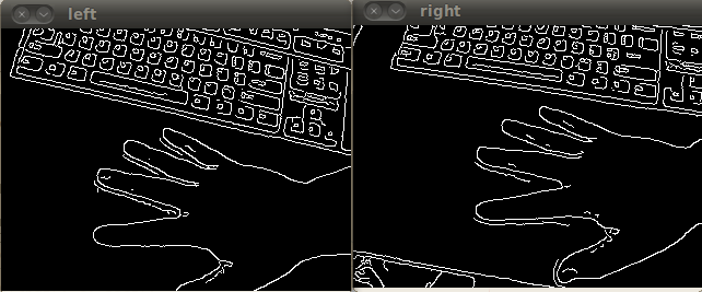
I have the two cameras working at the same time at 120+ frames per second. They are streaming the frames while applying a gaussian blur and a canny edge detection algorithm while only using a quarter of a Core2Duo CPU. Plenty of CPU cycles left for the stereo detection and all the other stuff.
I started by just streaming clean, non-altered images. This took quite a while since I am still getting familiar with OpenCV. Part of solution was to specify the size and depth of the image variable I was assigning the capture to. Other part was to keep the grabframe, retrieveframe, etc. functions in an infinite while loop.
This allows for non-drop frame captures while taxing the processor since I can keep all the stereo functions in this loop solving all of my potential syncing problems pre-emptively. Next, I attempted to add some image alteration functions in place, and failed miserably... After some research, I realized that my problem was a combination of namespaces and again CvMat size and depth. Now the code works fine with the blur and edge detection. I am in the process of implementing a non calibrated stereo rectification algorithm from OpenCV into the code.